CCG CW Captive Component Cable Gland (0512)
Product overview
CCG CW Captive Component Cable Gland
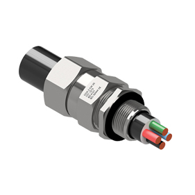
CCG CW Captive Component Gland is an Industrial Cable Gland Device with sealing on outer sheath, used to connect and secure Steel Wire Armoured (SWA) and Aluminium Armoured Cable to major equipment. For indoor and outdoor use.
CCG CW Part Numbers: 051200-16, 051200, 0512-0, 051201, 051222, 051202, 051233, 051203, 051244, 051204, 051255, 051205, 051266, 051206, 051277, 051207, 051288, 051208, 051299, 051209, 051210, 051211, 051212, 051213
Features & Benefits
- For indoor and outdoor use.
- Two piece handling, no loose parts.
- Freely rotating captive cone and inspectable cone ring, providing an inspectable armour clamp and earth bond without twisting the armouring.
- Patented disconnect armoured clamp system for ease of inspection.
- Provides a seal on the outer sheath of the cable sealing to IP65/66.
- Precision manufactured from high-quality brass (nickel plated) available in aluminium or stainless steel 316/316L on request.
- Complete with thread sealing gasket and heavy duty locknut.
CCG CW Technical Data
Type: CW Industrial Gland
Gland Material: Brass (Nickel Plated) BS 2874, EN 12164, Aluminium ASTM B221, Stainless Steel 316/316L
Seal Material: Thermoset Elastomer or Silicon on request
Cable Type: Steel Wire Armour and Aluminium Armour Wire
Armour Clamping: Rotating Captive Cone and Inspectable Cone Ring
Sealing Area: Outer Sheath
Optional Accessories: Adaptor, Reducer, Earth Tag, Locknut, Serrated Washer and Shroud
Installation Standards
- AS/NZS 3000
- BS 6121-5
- BS 7671
- BS 7430
- IEC 60364-5-54
- SANS 0142
Additional Technical Data of CCG CW Captive Component Cable Gland part numbers can be found on the table below. For Standards, Certifications & Fitting Instructions, please advise PDF Files.
FREE Technical Advisory Service
E-Tech Components UK Ltd maintains a free technical advisory service.
Contact us for enquiries concerning this and all other products: +44 (0) 1744 762 929
Interested in this Product?
+44 (0)1744 762 929Technical Data
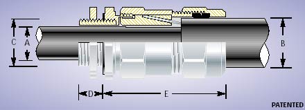
| Product Code | Gland Size Ref. | Metric Entry Thread (C) | Metric Entry Thread (Min D) | NPT Entry Thread (C) | NPT Entry Thread (Min D) | Cable Detail (Max A) | Cable Detail (Min B) | Cable Detail (Max B) | Max Length (E) | Armour Dia (Min F) |
Armour Dia (Max F) |
Hexagonal Detail (Max Flats) |
Hexagonal Detail (Max Crns) |
Installation Torque Value (Nm) |
| 051200-16 | ⊗* 00-16ss | M16 x 1.5 | 10 | - | - | 8.5 | 8.0 | 13.5 | 41.0 | 0.90 | 0.90 | ♠♥ 24 | ♥ 27 | 35.0 |
| 051200 | ⊗* 00-20ss | M20 x 1.5 | 10 | ½/¾ | 15 | 8.5 | 8.0 | 13.5 | 41.0 | 0.90 | 0.90 | ♠♥ 24 | ♥ 27 | 35.0 |
| 0512-0 | ⊗* 0-20s | M20 x 1.5 | 10 | ½/¾ | 15 | 12.0 | 11.5 | 16.0 | 43.0 | 0.90 | 1.25 | ♠♥ 24 | ♥ 27 | 35.0 |
| 051201 | * 1-20 | M20 x 1.5 | 10 | ½/¾ | 15 | 15.0 | 14.5 | 20.5 | 47.0 | 0.90 | 1.25 | ♠ 27 | 30 | 35.0 |
| 051222 | * 2s-25s | M25 x 1.5 | 10 | ¾/1 | 15/19 | 17.5 | 16 | 24.5 | 56.0 | 1.25 | 1.60 | ♠ 35 | 39 | 50.0 |
| 051202 | * 2-25 | M25 x 1.5 | 10 | ¾/1 | 15/19 | 20.0 | 20.5 | 26.5 | 56.0 | 1.25 | 1.60 | ♠ 35 | 39 | 50.0 |
| 051233 | * 3s-32s | M32 x 1.5 | 10 | 1/1¼ | 19 | 22.0 | 23.0 | 30.5 | 57.0 | 1.60 | 2.00 | ♠ 42 | 47 | 70.0 |
| 051203 | * 3-32 | M32 x 1.5 | 10 | 1/1¼ | 19 | 26.5 | 26.5 | 33.5 | 57.0 | 1.60 | 2.00 | ♠ 42 | 47 | 70.0 |
| 051244 | 4s-40s | M40 x 1.5 | 15 | 1¼/1½ | 19/21 | 31.5 | 30.0 | 39.5 | 68.0 | 1.60 | 2.00 | ♠ 52 | 59 | 90.0 |
| 051204 | 4-40 | M40 x 1.5 | 15 | 1¼/1½ | 19/21 | 34.0 | 33.0 | 42.5 | 68.0 | 1.60 | 2.00 | ♠ 52 | 59 | 90.0 |
| 051255 | 5s-50s | M50 x 1.5 | 15 | 1½/2 | 21 | 38.0 | 34.0 | 47.5 | 72.0 | 2.00 | 2.50 | ♠ 65 | 73 | 100.0 |
| 051205 | 5-50 | M50 x 1.5 | 15 | 1½/2 | 21 | 38.0/44.5 | 42.5 | 52.5 | 72.0 | 2.00 | 2.50 | ♠ 65 | 73 | 100.0 |
| 051266 | 6s-63s | M63 x 1.5 | 15 | 2/2½ | 21/30 | 50.0 | 45.5 | 60.5 | 89.0 | 2.00 | 2.50 | ♠ 80 | 90 | 120.0 |
| 051206 | 6-63 | M63 x 1.5 | 15 | 2/2½ | 21/30 | 50.0/56.5 | 52.5 | 65.5 | 89.0 | 2.00 | 2.50 | ♠ 80 | 90 | 120.0 |
| 051277 | 7s-75s | M75 x 1.5 | 15 | 2½/3 | 30/32 | 62.0 | 57.0 | 72.5 | 97.0 | 2.50 | 3.15 | ♠ 96 | 108 | 120.0 |
| 051207 | 7-75 | M75 x 1.5 | 15 | 2½/3 | 30/32 | 62.0/67.5 | 65.5 | 78.0 | 97.0 | 2.50 | 3.15 | ♠ 96 | 108 | 120.0 |
| 051288 | 8s-80s | M80 x 2.0 | 20 | 3 | 32 | 69.0 | 65.0 | 77.5 | 98.0 | 2.50 | 3.15 | ♠ 96 | 108 | 120.0 |
| 051208 | 8-80 | M80 x 2.0 | 20 | 3 | 32 | 74.0 | 78.0 | 82.0 | 98.0 | 2.50 | 3.15 | ♠ 96 | 108 | 120.0 |
| 051299 | 9s-90s | M90 x 2.0 | 20 | 3/3½ | 32/33 | 75.0 | 73.0 | 86.5 | 123.0 | 3.00 | 3.50 | ♠ 96 | 108 | 120.0 |
| 051209 | 9-90 | M90 x 2.0 | 20 | 3/3½ | 32/33 | 75.0/81.5 | 82.0 | 91.0 | 123.0 | 3.00 | 3.50 | ♠ - | - | 120.0 |
| 051210 | 10-100 | M100 x 2.0 | 20 | 3½/4 | 33/34 | 91.0 | 90.0 | 100.0 | 124.0 | 3.00 | 3.50 | ♦ - | - | 120.0 |
| 051211 | 11-110 | M110 x 2.0 | 20 | 4 | 34 | 98.0 | 100.0 | 114.0 | 134.0 | 3.00 | 4.00 | ♦ - | - | 120.0 |
| 051212 | 12-120 | M120 x 2.0 | 20 | - | - | 103.0 | 103.0 | 118.0 | 136.0 | 3.00 | 4.00 | ♦ - | - | 120.0 |
| 051213 | 13-130 | M130 x 2.0 | 20 | - | - | 115.0 | 113.0 | 124.0 | 140.0 | 3.00 | 4.00 | ♦ - | - | 120.0 |
|
All dimensions are in mm (apart from NPT). ⊗: Supplied with fixed cone and brush. * : For use with CCG Handi Fit Boxes ♠ : For use with a CCG Hex Spanner. ♦ : For use with a CCG C Spanner. ♥ : When manufactured in Aluminium, Hex will be 27 Across Flats and 30 Across Corners. |
 |

