Nexans GPH Mechanical Cable Connectors (up to 52kV)
Product overview
Nexans GPH Mechanical Cable Connectors
GPH Mechanical Cable Connectors (up to 52kV), with shear-off-head bolts and transverse grooving. Nexans makes the connector body from high-strength aluminium alloy, and the bolts from tin-plated brass, with inner and outer hexagons made from aluminium alloy. Connectors filled with compound and sealed in plastic.
Nexans Part Numbers: M16-95, M25-150, M70-240, M95-240, M95-300, M120-300, M185-400, M300-500, M400-630, M630-1000, M800, M1000, M800-1200.
Technical Data
Material:
Connector Body: high strength aluminium alloy
Bolts: brass, tin-plated, with inner and outer hexagon from aluminium alloy
Surface:
Connector Body: tin-plated
Centering:
The package includes centre rings or inserts to position the conductor centrally.
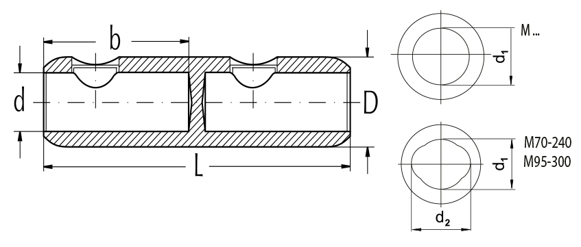
Additional Technical Data of Nexans GPH Mechanical Cable Connectors (M16-95, M95-300, M185-400, M400-630) can be found on the table below. For more information, please advise PDF File. Nexans 17JTS1 W
FREE Technical Advisory Service
E-Tech Components UK Ltd maintains a free technical advisory service.
Contact us for enquiries concerning this and all other products: +44 (0) 1744 762 929
Interested in this Product?
+44 (0)1744 762 929Technical Data
| Part No | Round Stranded Alu (mm2) |
Round Solid Alu (mm2) |
Sector Stranded Alu (mm2) |
Round Stranded Cu (mm2) |
Sector Stranded Cu (mm2) |
No of Bolts | L | d1 | D | b | Outer & Inner Hexagon Tool |
| M16-95 | 16-95 | 10-95 | 25-70 | 16-95 | 25-70 | 2 | 70 | 12.5 | 24 | 32 | SW10 & SW6 |
| M25-150 | 25-150 | 25-150 | 35-120 | 25-150 | 35-120 | 2 | 85 | 15.5 | 30 | 35 | SW10 & SW6 |
| M70-240 | 70-240 | 70-240 | 70-240 | 70-240 | 70-240 | 4 | 120 | 221 | 35 | 56 | SW13 & SW6 |
| M95-240 | 95-240 | 95-240 | 95-185 | 95-240 | 95-185 | 4 | 120 | 20 | 33 | 56 | SW13 & SW6 |
| M95-300 | 95-300 | 95-300 | 95-240 | 70-300 | 70-240 | 4 | 142 | 231 | 36 | 67 | SW13 & SW8 |
| M120-300 | 120-300 | 120-300 | 120-240 | 120-300 | 120-240 | 4 | 142 | 25 | 38 | 67 | SW19 & SW6 |
| M185-400 | 185-400 | 185-400 | 185-300 | 185-400 | 185-300 | 6 | 170 | 26 | 42 | 82 | SW19 & SW6 |
| M300-500 | 300-500 | 300-500 | 300-400 | 300-500 | 300-400 | 6 | 200 | 34 | 52 | 94 | SW19 & SW8 |
| M400-630 | 400-630 | 400-630 | 400-500 | 400-630 | 400-500 | 6 | 200 | 34 | 52 | 94 | SW19 & SW8 |
| M630-10002 | 630-1000 | 630-1000 | - | 630-1000 | - | 8 | 220 | 41 | 65 | 105 | SW19 & SW8 |
| M800 | 800 | 800 | - | 800 | - | 8 | 220 | 37 | 60 | 105 | SW19 |
| M1000 | 1000 | 1000 | - | - | - | 8 | 220 | 41 | 60 | 105 | SW19 |
| M800-12001 | 800-1200 | 630-1200 | - | 630-1000 | - | 8 | 220 | 45 | 72 | 105 | SW22 & SW8 |
 Notes: Notes:
1: Dimension d2 = 26 mm 2: Centric conductor positioning by center inserts |

