CCG A2F-H Compression Cable Gland (0449)

Product overview
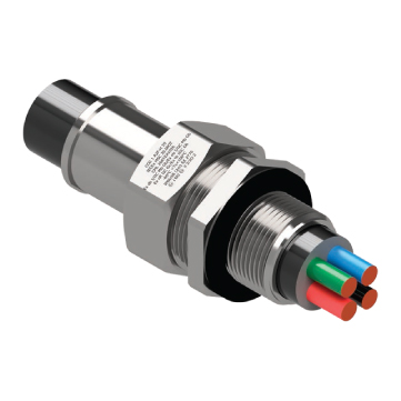
CCG A2F-H Compression Cable Gland (0449)
CCG A2F-H Compression Cable Gland (0449) is a Hazardous Area Glanding Device for Unarmoured Cable. Suitable for Group I, II, III, Zone 1, 2, 21 and 22 hazardous areas.
CCG Part Numbers: 044900-16, 044900, 0449-0, 044901, 044922, 044902, 044933, 044903, 044944, 044904, 044955, 044905, 044966, 044906, 044977, 044907
Features & Benefits
- For Group I, II, III, Zone 1, 2, 21 and 22 hazardous areas.
- Fitted with specially formulated elastomeric displacement seals, for superior cable retention, explosion protection and IP rating.
- A hose tail provides for clamping a protective hose over the cable.
- Precision manufactured from high-quality brass (Marine Grade Electroless Nickel Plated™) available in stainless steel 316/316L on request.
- Supplied with a thread sealing gasket (parallel threads only).
CCG A2F-H Technical Data
Type: A2F-H
Equipment Protection Levels: Ex db I/IIC, Ex eb I/IIC, Ex ta IIIC, Ex nR IIC
Gland Material: Brass (Marine Grade Electroless Nickel Plated™), Stainless Steel 316/316L
Seal Material: Standard Thermoset Elastomer or Extreme Temperature Seals
Sealing Gasket Material: HDPE, Nylon 66 or PTFE
Cable Type: Unarmoured
Sealing Area: Outer Sheath
Optional Accessories: Adaptor, Reducer, Earth Tag, Locknut, Serrated Washer and Shroud
Note: The installer should ensure that the materials are suitable for the installation environment.
Installation Standards
- IEC/BS EN
- IECEx
- ATEX
- UKEX
- INMETRO (Brazil)
- TR CU (Russia)
- CCC/CNEx (China)
- SANS
- Ingress Protection
- Deluge Protection
- Corrosion Protection
- Marine ABS
- DNV-GL
Hazardous Areas
A Hazardous Area is one in which there is potential for an explosion of gases, vapours, mists or dust or a combination of these. Such locations are petrochemical plants, offshore oil rigs, fuel filling stations, timber mills, coal mines, flour mills, paint spray booths, sewerage treatment plants, hospitals, explosive magazines and more.
Special precautions must be taken for the design, manufacture, installation and use of equipment and cable glands in such hazardous areas. Persons involved in selecting installing and maintaining electrical equipment for use in hazardous areas should be competently trained, have a full understanding of what a hazardous area is and have knowledge of the equipment protection levels and the installation standards involved.
Additional Technical Data on CCG A2F-H Compression Cable Gland (0449) Part Numbers can be found on the table below. For Conforming Standards & Certificates as well as Fitting Instructions, please advise PDF File.
FREE Technical Advisory Service
E-Tech Components UK Ltd maintains a free technical advisory service.
Contact us for enquiries concerning this and all other products: +44 (0) 1744 762 929
Interested in this Product?
+44 (0)1744 762 929Technical Data
| Product Code | Gland Size Ref. | Metric Entry Thread (C) | Metric Entry Thread (Min D) | NPT Entry Thread (C) | NPT Entry Thread (Min D) | Cable Detail (Min A) | Cable Detail (Max A) | Max Length (E) | Spigot/ Hose Tail (B) | Hexagonal Detail (Max Flats) |
Hexagonal Detail (Max Crns) |
Installation Torque Value (Nm) |
| 044900-16 | 00-16ss | M16x1.5 | 15 | - | 15 | 3 | 8.5 | 63 | 19 | 24 | 27 | 32.5 |
| 044900 | 00-20ss | M20x1.5 | 15 | ½/¾ | 15 | 3 | 8.5 | 63 | 19 | 24 | 27 | 32.5 |
| 0449-0 | 0-20s | M20x1.5 | 15 | ½/¾ | 15 | 7 | 12 | 63 | 19 | 24 | 27 | 32.5 |
| 044901 | 1-20 | M20x1.5 | 15 | ½/¾ | 15 | 11 | 14.5 | 77 | 19 | 27 | 30 | 32.5 |
| 044922 | 2s-25s | M25x1.5 | 15 | ¾/1 | 15/19 | 11.5 | 17.5 | 77.5 | 25.4 | 35 | 39 | 47.5 |
| 044902 | 2-25 | M25x1.5 | 15 | ¾/1 | 15/19 | 15 | 20 | 77.5 | 25.4 | 35 | 39 | 47.5 |
| 044933 | 3s-32s | M32x1.5 | 15 | 1/1¼ | 19 | 16 | 22 | 91 | 31.8 | 42 | 47 | 55 |
| 044903 | 3-32 | M32x1.5 | 15 | 1/1¼ | 19 | 20 | 26.5 | 91 | 31.8 | 42 | 47 | 55 |
| 044944 | 4s-40s | M40x1.5 | 15 | 1¼/1½ | 19/21 | 22 | 31.5 | 109 | 38.1 | 52 | 59 | 65 |
| 044904 | 4-40 | M40x1.5 | 15 | 1¼/1½ | 19/21 | 26 | 34 | 109 | 38.1 | 52 | 59 | 65 |
| 044955 | 5s-50s | M50x1.5 | 15 | 1½/2 | 21 | 29 | 38 | 136 | 50.8 | 65 | 73 | 82.5 |
| 044905 | 5-50 | M50x1.5 | 15 | 1½/2 | 21 | 34 | 44.5 | 136 | 50.8 | 65 | 73 | 82.5 |
| 044966 | 6s-63s | M63x1.5 | 15 | 2/2½ | 21/30 | 38 | 50 | 161 | 63.5 | 80 | 90 | 97.5 |
| 044906 | 6-63 | M63x1.5 | 15 | 2/2½ | 21/30 | 44.5 | 56.5 | 161 | 63.5 | 80 | 90 | 97.5 |
| 044977 | 7s-75s | M75x1.5 | 15 | 2½/3 | 30/32 | 50 | 62 | 181 | 76 | 96 | 108 | 115.5 |
| 044907 | 7-75 | M75x1.5 | 15 | 2½/3 | 30/32 | 56 | 67.5 | 181 | 76 | 96 | 108 | 115.5 |
|
All dimensions are in mm (apart from NPT). Intermediate thread sizes are available on request. NPT threads should be tightened ‘wrench tight’. |