What are Cable Cleats? The Definitive Guide
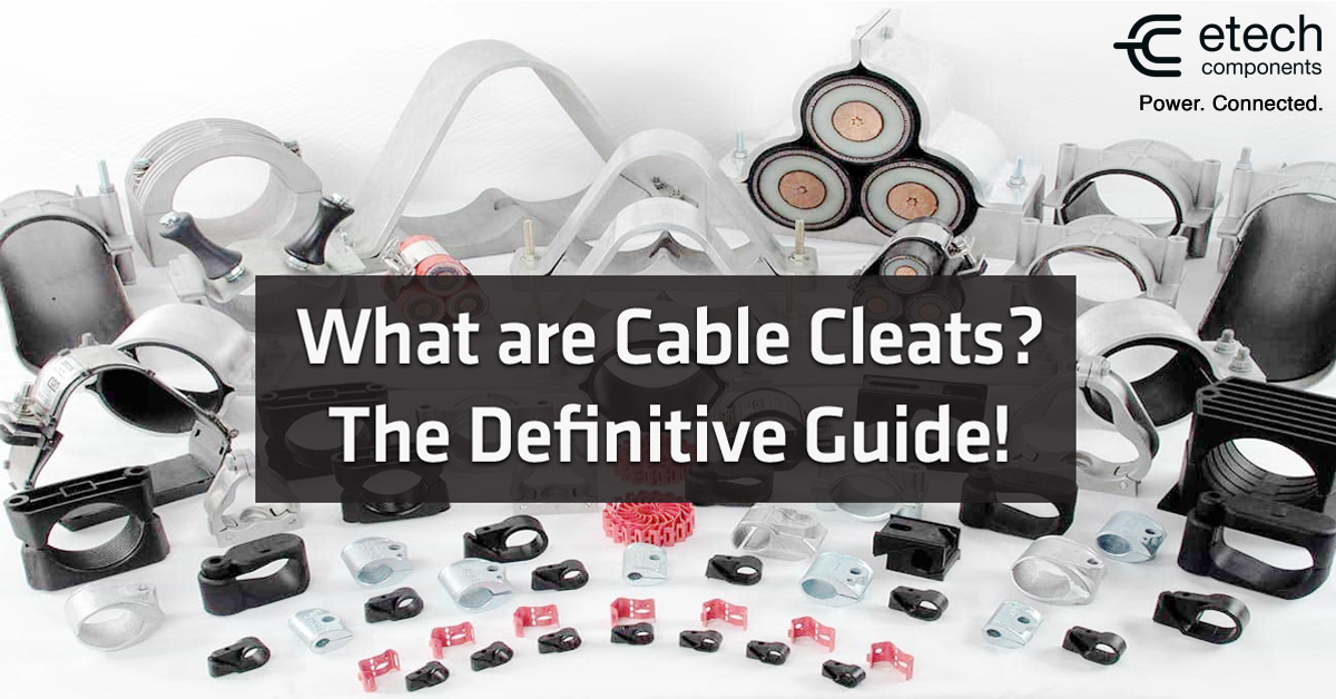
Table of Contents
- What are Cable Cleats?
- Why use Cable Cleats?
- Types of Cable Cleats
- Choosing the Right Cable Cleat
- Cable Cleats in Action: Real-World Applications
- Bespoke and Complex Cable Arrangements
- Cable Cleat Specification
- Dealing with Thermal Expansion and Cable Movement
- How to Fix / Install Cable Cleats?
- Correct Cleat Spacing
- E-Tech Components – Cable Management & Cleating
What are Cable Cleats?
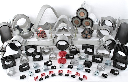
Cable cleats (also called cable clamps) are an essential component in any electrical installation. Ultimately, they secure cables safely and effectively. This article answers frequently asked questions about Cable Clamps and Cleats, including: “what are cable cleats?”, “when to use cable cleats”, “cable cleat types & specification”, “correct cleat spacing”, “how to fix cable cleats” and more.
According to IEC 61914:2009, Cable Cleats are “devices designed to provide securing of cables when installed at intervals along the length of the cables”. Simply put, they retain and support cables, restrict movement and provide resistance to electro-mechanical forces.
Why use Cable Cleats?
Cable cleats ensure that cables are fixed, retained and supported correctly. In the event of a short circuit or other electrical fault, properly secured cables will remain in place without causing damage. This allows the circuit to be safely restored.
Failing to clamp cables correctly can disrupt the flow of electricity and lead to serious consequences. In addition to this, cable cleats and clamps are also important because they:
- Support cables and conductors, preventing excessive movement and making maintenance safer and easier
- Provide restraint and protect against electro-dynamic forces that develop during short circuits or earth faults
- Reduce mechanical stress on cables from their own weight and from loads at cable terminations
- Enable a neat and orderly installation, allowing cables to operate at their optimum ratings while maximising available space
- Secure cables to mounting surfaces – such as ladders, trays, struts, rails, wires or beams – without relying on the surface itself for cable retention
When are They Required?
Despite their critical role in electrical safety, cable cleats / clamps lacked British or international standards for many years. Prysmian Components, a leading manufacturer, actively contributed to the development of the European Standard, which later evolved into the current International Standard (BS EN 61914:2009 – IEC 61914). This standard formally recognised the importance of cable cleat / clamp products. Specifying correct cleat fixing and spacing, it also emphasised the protection of management systems. Most importantly, it showed that failing to use cable cleats or clamps can put human life at risk in installations.
Selecting the right cleats isn’t just about size and material — it’s about meeting essential safety and performance standards. In the UK and Europe, BS EN 61914 defines the testing and performance criteria for cable cleats / clamps. This includes mechanical load capacity and short-circuit withstand forces. Compliance ensures that cleats can safely restrain cables during fault conditions, protecting both personnel and equipment.
Other relevant standards include:
– BS 8434: Covers metallic cable management systems, including trays, supports and cleats
– BS EN 50575: Relates to the fire performance of cables, ensuring cleat materials are compatible with the cable’s rating, such as FR, LSF or LSZH
Using cable cleats that comply with these standards is not just best practice. It is often a legal and safety requirement in modern installations, ensuring both reliability and protection.
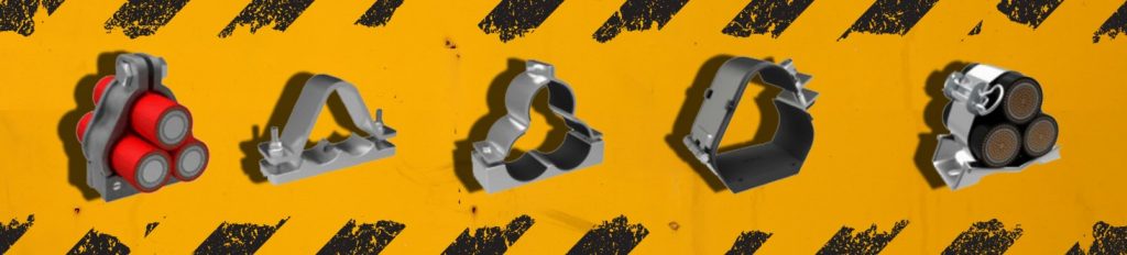
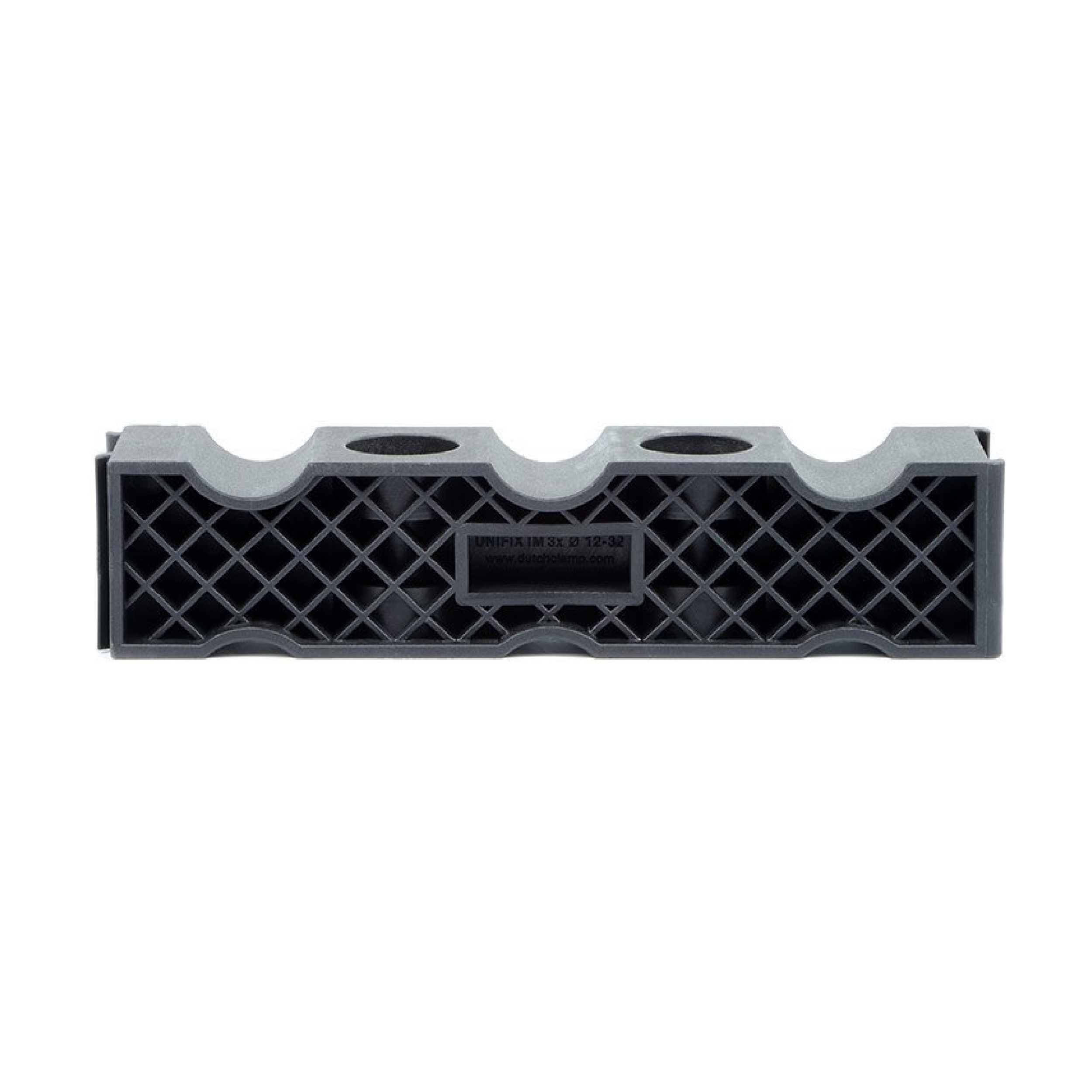
Types of Cable Cleats
Manufacturers generally divide cleats into two main types: metal and plastic, each offering distinct advantages and suited to different applications. Understanding cable cleat types helps ensure you select the right solution for your installation requirements.
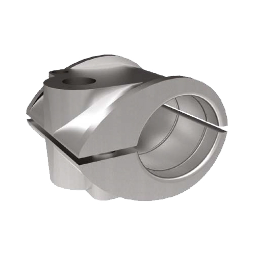
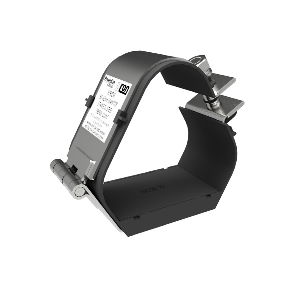
Metal cable cleats, such as the Prysmian Single Way Claw Cleat (370BA) made from aluminium alloy, are ideal for securely fastening single cables. Options include non-conductive aluminium and stainless steel, with advanced designs like the Prysmian Sirius Trefoil Cleat (379TC) featuring a LSOH (low smoke, zero halogen) lining for enhanced safety.
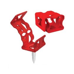
Plastic cable cleats, exemplified by the Prysmian Single Way Telcleat (385AA), provide flexibility for a range of cable diameters. Their UV- and weather-resistant fixing points allow for double stacking, enabling two cables to be secured on a single mount. With wide operating temperature ranges and excellent durability, plastic cleats offer a cost-effective and reliable solution for demanding environments.
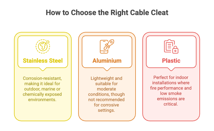
Choosing the right cable cleat goes beyond simply knowing the cable cleat types available. It’s about understanding the specific performance requirements, environmental conditions and cable configuration for your installation.
Choosing the Right Cable Cleat
Some of the most common questions our Sales team hears are:
“Which cable cleating should I use?”
“What size cable cleat do I need for…?”
The answer is always the same: “It depends”.
At E-Tech Components, we offer an extensive range of single, trefoil and quad cleats, as well as bespoke solutions. Every product is designed and manufactured to meet the specific requirements of the application, sourced from leading industry cleat manufacturers.
Choosing the right cable cleat goes beyond size and type. It’s also about ensuring dependable performance in the environment where it will be installed. Factors such as temperature, UV exposure, chemical contact and moisture can all impact cleat performance.
Matching the cleat material to the installation environment enhances durability, extends service life and reduces long-term maintenance costs.
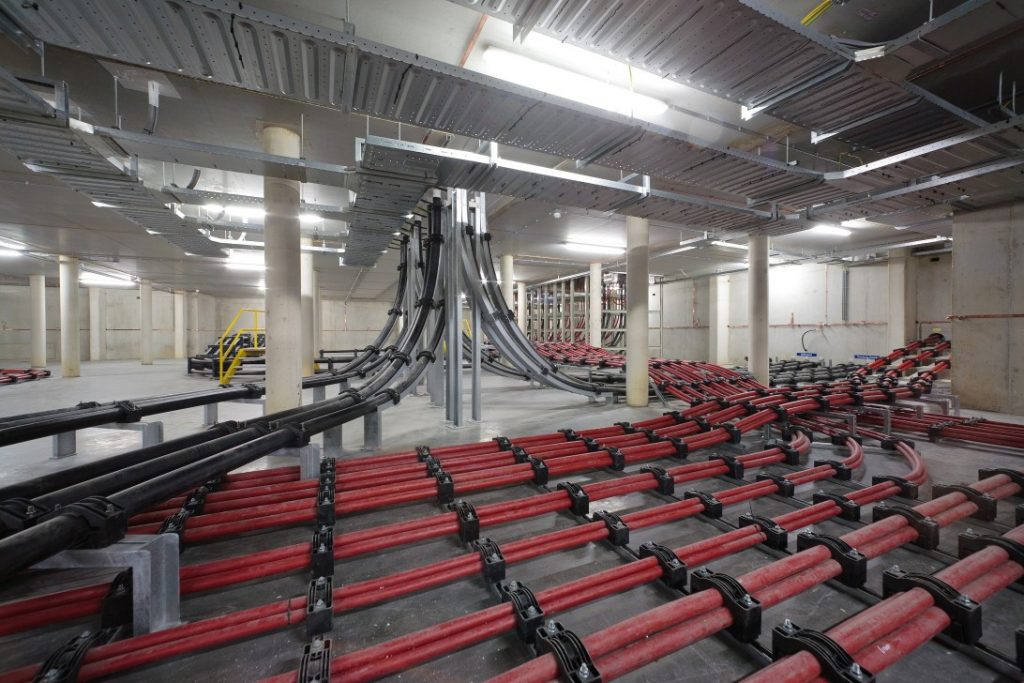
Cable Cleats in Action: Real-World Applications
Data Centres: In high-density, high-power installations, cable cleats play a vital role in securing LV, MV and HV power cables. Properly fixed cables maintain airflow for thermal management, prevent movement during electrical faults and reduce the risk of short circuits or fire. Well-organised cabling also simplifies maintenance and upgrades, minimising downtime in constantly evolving infrastructures. Cleats should be chosen for their ability to withstand high short-circuit forces, resist corrosion and adapt to bespoke arrangements. Selecting the right cleats ensures compliance with standards such as IEC 61914, while also safeguarding both infrastructure and personnel.
Industrial Facilities: Heavy machinery and long cable runs generate high mechanical loads. This makes cleats essential for reducing stress on cable terminations and supporting safe operations.
Renewable Energy and Nuclear Sectors: In wind, solar, battery energy storage systems (BESS) and nuclear installations, cleats play a critical role in securing high voltage and high current cables. They ensure safety under dynamic loads, resist environmental and mechanical stresses, and support long-term system reliability.
Outdoor Installations: Exposed environments require cleats that withstand wind, rain, UV exposure, and temperature extremes, ensuring long-term reliability and protection.
Bespoke and Complex Cable Arrangements
While standard cleats suit most installations, trefoil formations, quad bundles or unique tray layouts may require bespoke cleats. Custom-designed cleats can ensure:
– Full containment of cables during short-circuit events
– Correct spacing for non-standard cable arrangements
– Compatibility with specialised supports, ladder racks or constrained spaces
Here at E-Tech, our bespoke solutions ensure even the most complex installations are safe, reliable and fully compliant.
Cable Cleat Specification
You should consider several key factors to specify the perfect cleat for your application:
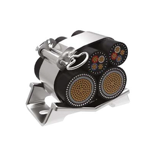
- Cable Formation: The configuration of the cable system — whether parallel/flat formation of single-core cables, trefoil formation, or multicore cable — determines the type of cleat required. This could be a single, trefoil or quad cleat and in some cases, a bespoke solution may be necessary for precise cable cleat specification.
- Cable Type: The type of cable, whether single or multicore, is a critical consideration. Voltage level and construction — Low Voltage (LV), Medium Voltage (MV) or High Voltage (HV) — also influence cleat selection.
- Cable Diameter: The overall diameter of the LV or HV cable helps identify the correct cleat size. The outside diameter of the cable sheath is also used to calculate the short-circuit forces the cleat may experience under fault conditions.
- Performance Requirements: Depending on the installation, cleats may need to meet specific material and performance standards, such as Fire Resistance (FR), Low Smoke Zero Halogen (LS0H/LSZH), Low Smoke & Fume (LSF) or corrosion resistance (stainless steel).
- Short Circuit Rating: The maximum peak fault current (kA) that the cable may experience under short-circuit conditions is a critical factor in cable cleat specification.
- Expansion & Contraction: Some cables expand and contract more than others due to temperature changes. Constraining the cable can transfer significant forces to the supporting structure. For single-core cables, installers often incorporate slight loops (“snaking”) to accommodate this expansion and contraction.
- Other Considerations: Power system design, mechanical load, cable management structure and the installation environment also play important roles in the specification.
Dealing with Thermal Expansion and Cable Movement
Cables naturally expand and contract with temperature fluctuations, particularly single-core types. Rigid cleating can transfer considerable forces to the supporting structure, potentially causing mechanical stress or damage. Therefore, best practice includes:
– Slightly “snaking” single-core cables to accommodate thermal expansion
– Leaving selected cleats free to slide along long cable runs
– Planning placement carefully around bends, vertical runs and changes in elevation
Incorporating thermal movement into cleat planning ensures the system remains secure and reduces the risk of mechanical failure.
How to Fix / Install Cable Cleats?
Selecting the correct cable cleat specification is only one part of the job. Cable system designers and installers must also carefully consider how cables are fixed and installed in the cleats to effectively restrain cable movement, whether caused by electrical faults or other forces. As a general rule, cleats should be firmly secured using supports strong enough to withstand forces corresponding to the peak prospective short-circuit current.
Installers typically fasten cleats around cables using a threaded bolt and nut. The higher the torque applied, the tighter the cleat grips the cable. While a firm grip helps prevent axial slippage, over-tightening can damage both the cable’s outer sheath and its internal construction.
>
How to Fix Cable Cleats – Our Recommendation: Tighten the cleat fixings so they fit snugly around the cable, leaving no gaps between the liner and the cable. Make sure the outer jacket shows no visible damage or bulging.
Correct Cleat Spacing
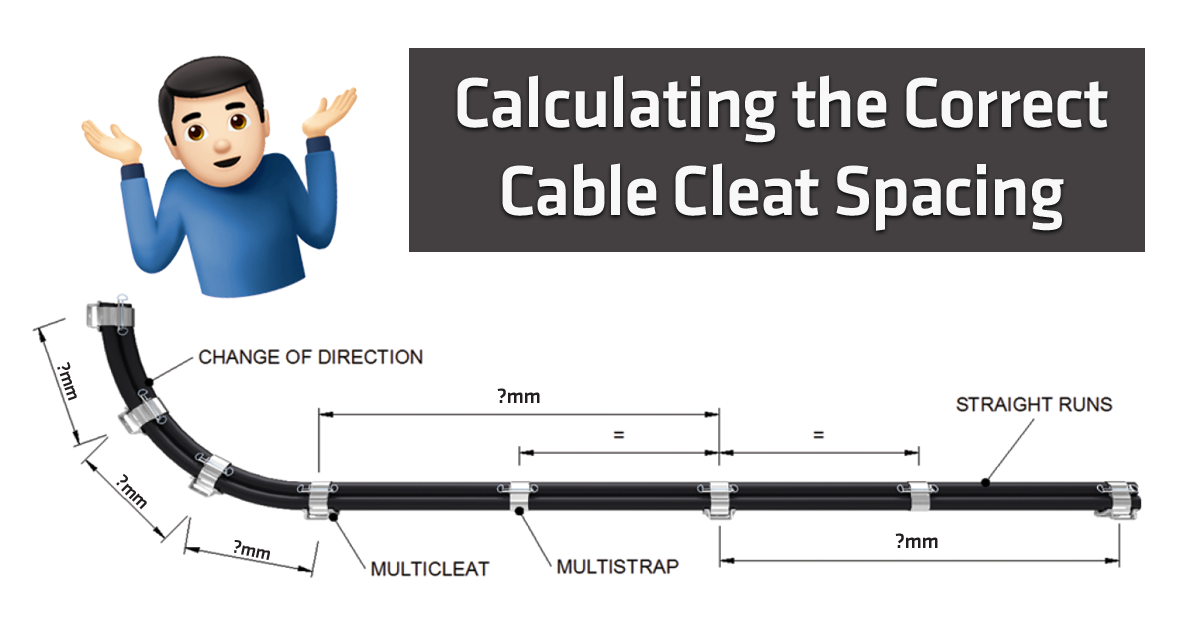
Single Cables
Correct Cable Cleat Spacing in accessible positions:

Notes:
- Installer should use fire resistant fixings for fire resistant cables
- For flat cables taken as the dimension of the major axis
- The spacings shown above apply to multi-core cables
- The spacing of fixings on single core cables in a.c. installations must take account of the magnitude of forces generated under fault conditions
- You can use the spacings stated for horizontal runs to runs angled at more than 30° from the vertical
- For runs at an angle of 30° or less from the vertical, spacing suggestions are applicable
Trefoil Cables
When a short-circuit fault occurs in a three-phase system, the current initially experiences a period of extreme asymmetry before settling into a more balanced, symmetric state.
The degree of asymmetry depends both on the point in the cycle when the fault occurs and on the nature of the fault itself (e.g., three-phase to earth). By convention, the “peak” refers to the maximum current value during this early asymmetrical period, which is also when the highest instantaneous forces act between the cables.
When the system’s peak fault current and the cable diameter are known, BS EN 61914:2009 (IEC 61914) provides a formula to calculate the maximum force exerted on a cable conductor.
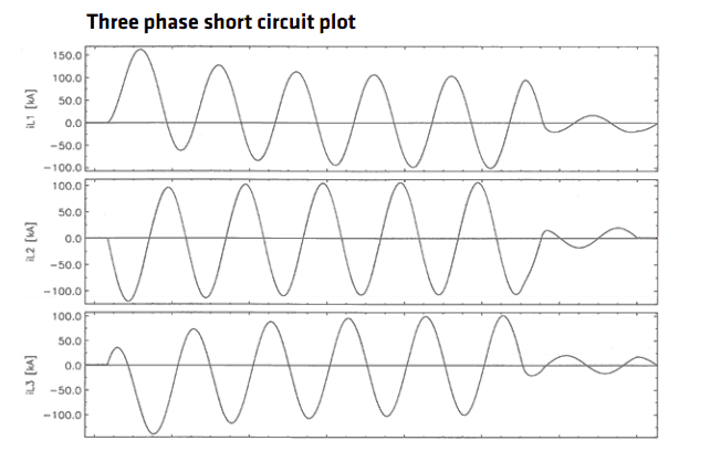
Ft= 0.17 x ip2 / S (B.4)
Where:
Ft is the maximum force on the cable conductor in a trefoil configuration for a three phase short circuit [N/m]
ip is the peak short-circuit current [kA]
S is the centre to centre distance between two neighbouring conductors [m] (for Trefoil arrangements S=Cable Diameter)
Short circuit tests in accordance with BS EN 61914:2009 take place on the most critical cleat size within its range. The Formulas (B.4) used can then calculate the maximum F during the test. You can then use this maximum force figure when specifying alternative configurations of the cable size and fault current. Calculate the theoretical Ft for the alternative configuration and ensure it is smaller or equal to the tested value.
Trefoil Cable Cleat Spacing
Trefoil Cleats designed to withstand the high forces generated by short-circuit currents are typically spaced at regular intervals. They are often aligned with standard cable ladder spacings (e.g., 225 mm or 300 mm).
The maximum short-circuit current ratings for each trefoil cleat design are provided with the manufacturer’s test data. For systems with larger cables or lower fault currents, it may be possible to increase these spacings. Our Technical Team can advise on this.
As a general guideline, you should install cleats or straps no more than 900 mm apart. This ensures a safe and reliable trefoil installation.
E-Tech Components – Cable Management & Cleating
E-Tech Components offers an extensive range of cleats and clamps, from Single and Trefoil to Quad Cleats and Bespoke Solutions. They are all designed and manufactured to meet your specific application requirements.
We partner with leading global cable manufacturers, including The Prysmian Group, distributing to major projects worldwide. Prysmian’s BICON range of cable cleats and clamps is tried, tested and certified to the latest international standards. We also collaborate with Slagboom Electric, offering their Dutchclamp range of non-metallic Single Way and Trefoil Cleats.
With such a comprehensive portfolio, our Technical Sales Team will help you select the ideal cleat for your installation. From cable cleat specification to sizing and types, we have the answers you need.
FREE Technical Advisory Service
E-Tech Components UK Ltd maintains a free technical advisory service.
Contact us about any questions, enquiries or requests you may have: +44 (0) 1744 762 929