Calculating the Correct Cable Cleat Spacing
Calculate Correct Cable Cleat Spacing
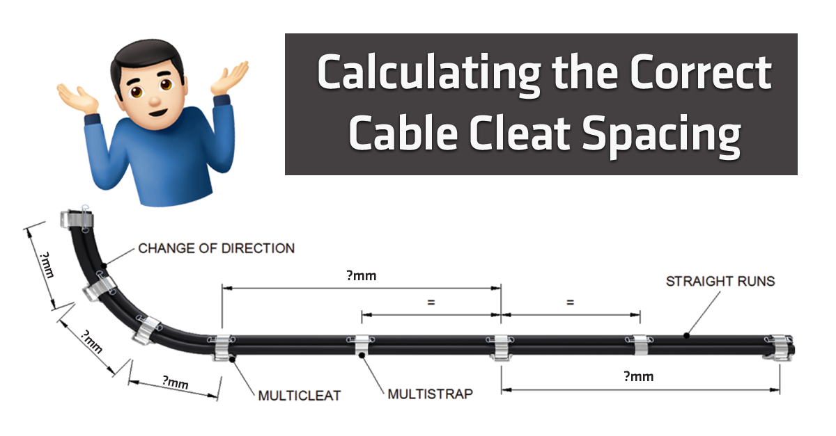
The way to calculate the Correct Cable Cleat Spacing (or other fixing spacing) differs depending on whether it is a Single or a Trefoil Cleat Spacing that you are after. In the tables and formulas below, you can find the best way to calculate the maximum distance / spacing between cable cleat fixings.
Single Cables
| MAXIMUM SPACING OF CABLE CLEATS & FIXINGS | ||||||
| Overall Diameter of cable² (OD) |
Non-armoured thermosetting, thermoplastic or lead sheathed cables and non-armoured fire resisting cables |
Single-wire armoured cables including fire resisting armoured cable |
Mineral insulated copper sheathed or Aluminium sheathed cables |
|||
| Horizontal5 2 | Vertical5 3 | Horizontal5 6 | Vertical5 7 | Horizontal5 8 | Vertical5 9 | |
| OD ≤ 9 mm | 250 mm | 400 mm | – | – | 600 mm | 800 mm |
| 9 mm < OD ≤ 15 mm | 300 mm | 400 mm | 350 mm | 450 mm | 900 mm | 1200 mm |
| 15 mm < OD ≤ 20 mm | 350 mm | 450 mm | 400 mm | 550 mm | 1500 mm | 2000 mm |
| 20 mm < OD ≤ 40 mm | 400 mm | 550 mm | 450 mm | 600 mm | – | – |
| 40 mm < OD ≤ 50 mm | 600 mm | 800 mm | 900 mm | 1100 mm | – | – |
| 50 mm < OD ≤ 60 mm | 750 mm | 1000 mm | 950 mm | 1100 mm | – | – |
| 60 mm < OD ≤ 70 mm | 900 mm | 1200 mm | 1000 mm | 1200 mm | – | – |
| OD ≥ 70 mm | 1000 mm | 1400 mm | 1200 mm | 1400 mm | – | – |
Notes:
- You should use fire-resistant fixings for fire-resistant cables.
- For flat cables taken as the dimension of the major axis.
- The spacings shown above apply to multi-core cables.
- The spacing of fixings on single core cables in a.c. installations must take account of the magnitude of forces generated under fault conditions.
- You can apply the spacings stated for horizontal runs to runs angled more than 30° from the vertical.
- For runs at an angle of 30° or less from the vertical, spacing suggestions are applicable.
Cleating Cables in Trefoil
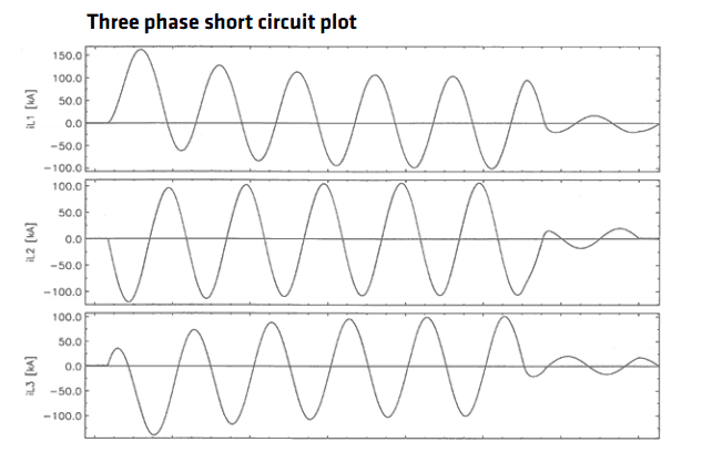
When a short circuit fault occurs in a three phase system, it first produces a period of extreme asymmetry, and then it shifts into a steadier, more symmetric state.
The degree of asymmetry depends on when in the cycle the fault is initiated and also the nature of the fault, e.g. three phase to earth. By convention, the “Peak” is the maximum current value achieved in the early asymmetrical period and it is at this point that the highest instantaneous force between the cables occurs.
When engineers know the system peak fault current and the cable diameter, BS EN 61914:2009 (IEC 61914) provides a formula that allows them to calculate the maximum force on a cable conductor.
Ft= 0.17 x ip2 / S (B.4)
Where:
Ft is the maximum force on the cable conductor in a trefoil configuration for a three phase short circuit [N/m]
ip is the peak short-circuit current [kA]
S is the centre to centre distance between two neighbouring conductors [m] (for Trefoil arrangements S=Cable Diameter)
Short circuit tests in accordance with BS EN 61914:2009 are performed on the most critical cleat size within its range; the Formula (B.4) can then be used to calculate the maximum F generated during the test. This maximum force figure can then be used when specifying alternative configurations of the cable size and fault current – calculating the theoretical Ft for the alternative configuration and ensuring that it is less than or equal to the as tested value.
Calculate Trefoil Cable Cleat Spacing
Engineers often space Trefoil Cleats at very regular intervals when the cleats must withstand the high forces generated by high short-circuit currents. They typically match the spacing of commonly available cable ladders (i.e., 300 mm / 225 mm).
The test information for each trefoil cleat design lists the maximum short-circuit current values. If a system uses larger cables or has a lower fault current, you may be able to increase the spacing between cleats
(Contact our Technical Team for help)
As a general rule, you should use a maximum trefoil cleat spacing of 900 mm to create and maintain a satisfactory trefoil installation.
For more information and answers to Frequently Asked Questions on Cable Clamps and Cleats (like “what are cable cleats?”, “when are cable cleats used?”, “cable cleat specification”, “how to fix cable cleats“ and more follow the link: What are Cable Cleats? The Definitive Guide
FREE Technical Advisory Service
E-Tech Components UK Ltd maintains a free technical advisory service.
Contact us about any questions, enquiries or requests you may have: +44 (0) 1744 762 929