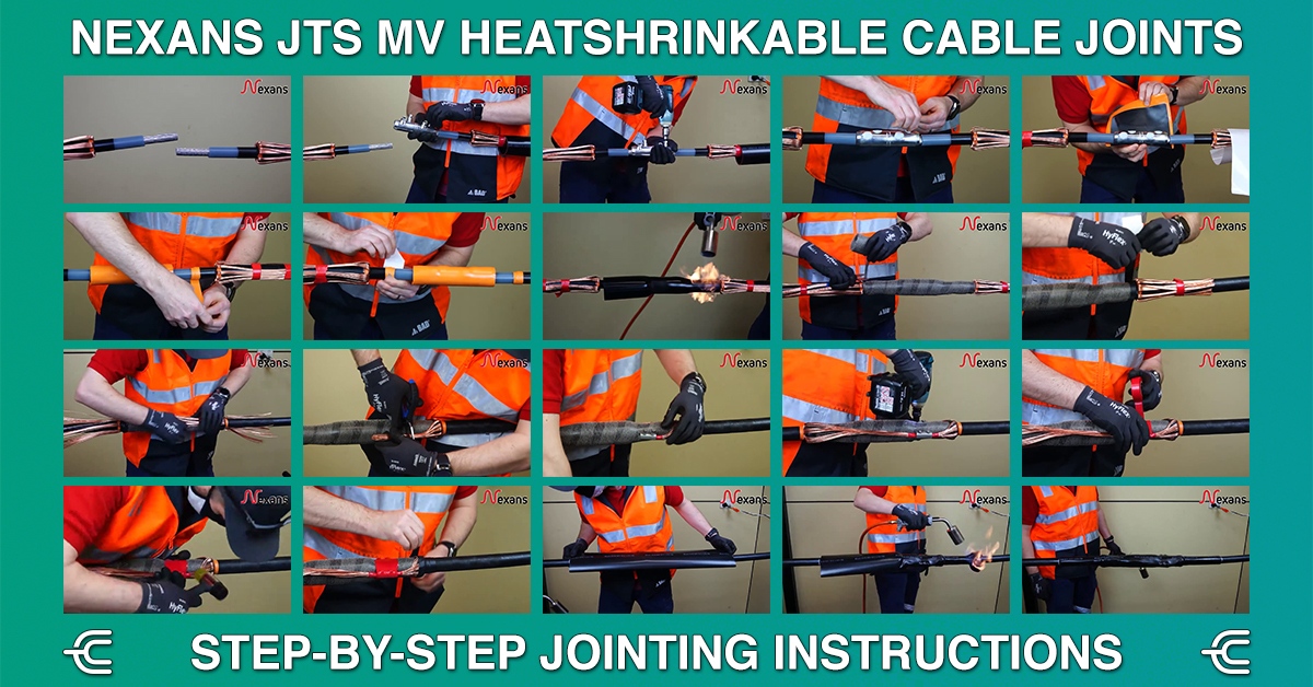
Step-by-Step Jointing Instructions for Nexans JTS Heatshrinkable MV Cable Joints
Nexans JTS Heatshrinkable MV Cable Joints
Nexans JTS range of Heatshrinkable MV Cable Joints consists of high performance, compact and easy-to-install Straight Cable Joints with Triple Wall Tube Technology. This technology allows installers to heat only one tube instead of three for 12 to 24kV applications, and two tubes instead of three for 36 to 42kV applications. This innovative solution simplifies and shortens the installation process and minimises the risk of joint failure. In this guide, we’ll walk you through the necessary steps for preparing and jointing cable with JTS, but also give you some technical tips on the installation instructions.
DISCLAIMER: At this point, we need to highlight that the installation of the JTS range or any cable joint should be performed by competent personnel, familiar with electrical equipment and safe operating practices. Additionally, all parts of the kit should be visually inspected for possible damage and installed in accordance with the manufacturer’s instructions. This guide and following the below instructions DO NOT substitute adequate cable jointing training!
Key Features & Benefits
Nexans JTS range of innovative Heatshrinkable Medium Voltage Cable Joints bring a vast number of features and operational benefits, including:
- Quick and Easy to install saving labour time, with no additional retraining required.
- Short and Slim design with impressive range taking sizes.
- Eliminates typical jointer errors.
- Excellent Insulating Properties for safer installations.
- Advanced Screen Connection & Armour Continuity for maximum control of fault currents.
- Thick Walled Tubing for High Mechanical Strength and Impact Resistance.
- Protection against Water Penetration & Chemical Aggression.
- Stabilised UV Protection for outdoor longevity.
- Halogen Free Material for safer use in enclosed spaces.
- Made to measure Fire Resistant blankets if required.
- LSOH outer sheath as standard.
- Fits single core and three core MV cables up to 36kV.
Termination Kits – Typical kit contents
Termination kits are engineered for reliability in the most demanding service environments. Designed for use with LV and MV power cables, these kits are ideal for both indoor and outdoor terminations, including installations exposed to high humidity, intense UV radiation, heavy pollution and fluctuating temperatures. Supplied in a pre-expanded state, all components shrink tightly around the cable upon application of heat, delivering a compact and durable seal.
Each termination kit typically includes the following components, selected to ensure electrical integrity, mechanical strength and environmental resilience.
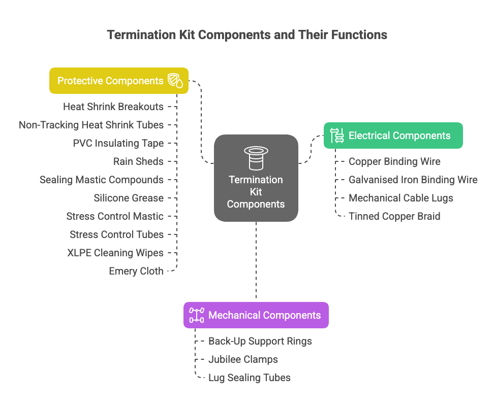
Protective Components:
Heat Shrink Breakouts
These ensure each core is individually sealed and protected at the branching point, providing mechanical support and environmental protection.
Non-Tracking Heat Shrink Tubes
These high-performance tubes are tailored for medium voltage terminations and provide excellent resistance to tracking, erosion and surface discharge. Their flexible, split-resistant construction allows easy installation over irregular shapes and bends, making them suitable for both indoor and outdoor use.
PVC Insulating Tape
Used for bundling, insulation enhancement, and as part of the overall joint structure for added mechanical stability.
Rain Sheds (Sheds for Outdoor Terminations)
Fitted over the termination assembly to shed water and prevent moisture build-up – especially critical for installations in wet or polluted environments.
Sealing Mastic Compounds (including Black Sealing Mastic)
Flexible and moisture-resistant sealing materials that conform to cable contours and offer robust protection against water ingress and environmental exposure.
Silicone Grease
Applied to reduce friction during the installation process and enhance water resistance within the termination.
Stress Control Mastic
A pliable compound used to smooth out transitions and fill voids around the semi-conductive screen and connectors, enhancing dielectric integrity.
Stress Control Tubes
Used to manage electrical field distribution where the cable screen is interrupted, these tubes minimise stress concentrations that can lead to premature failure. Manufactured from specially formulated polyolefin, they offer superior electrical grading and reliable long-term performance.
XLPE Cleaning Wipes
Impregnated with solvent to thoroughly clean and degrease the XLPE insulation before applying mastic or other components.
Emery Cloth
Supplied for abrading the cable insulation to ensure proper adhesion of mastic, tapes or heatshrink materials.
Electrical Components:
Copper Binding Wire (Cu)
Used to secure cable cores during termination while providing additional mechanical strength.
Galvanised Iron Binding Wire (GI Wire)
Used for mechanical fastening and grounding purposes, providing corrosion-resistant performance in outdoor applications.
Mechanical Cable Lugs
High-conductivity connectors included to provide dependable electrical performance under load and fault conditions.
Tinned Copper Braid
Provides effective shielding against electrical interference and facilitates the carrying of fault current safely to ground.
Mechanical Components:
Back-Up Support Rings
These stabilise the cable ends and reinforce critical sealing points, helping to maintain the shape and integrity of the termination under load and thermal stress.
Jubilee Clamps
Adjustable metal clamps that hold kit components securely in place throughout the service life of the termination.
Lug Sealing Tubes
Installed at the interface between the termination lug and the MV insulation tube, these tubes ensure a moisture-resistant seal and enhanced mechanical protection.
Cable Preparation Instructions – How to prepare cable for jointing
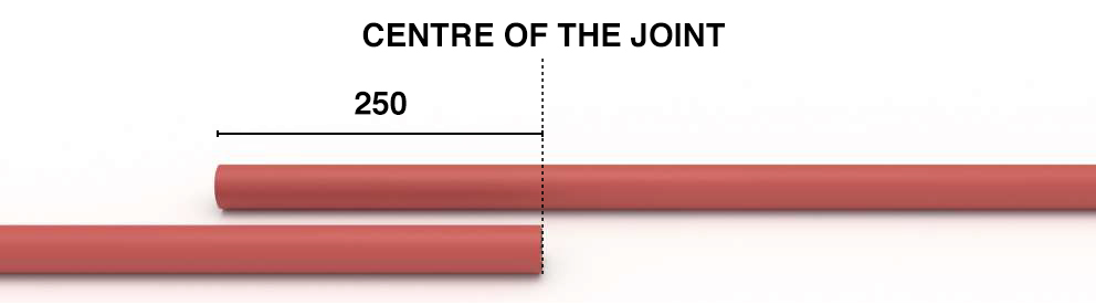 |
STEP 1:
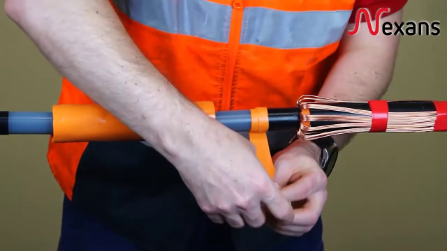
Straighten and set cables at the joint position. Determine the centre of the joint and cut one cable to length. Cut the other cable with a 250 mm overlap. Clean both outer sheaths for 1 metre. |
|
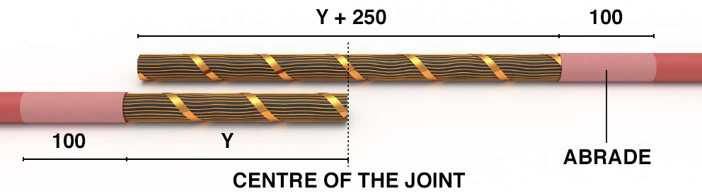 |
STEP 2: Remove the outer sheath for a distance “Y” as listed below, for one cable and “Y” plus 250 mm for the other cable. Y = 170mm for “Triple Wall” Tube Length of 300mm Then, abrade the outer sheath on both cables for a distance of 100 mm and clean the abraded area. |
|
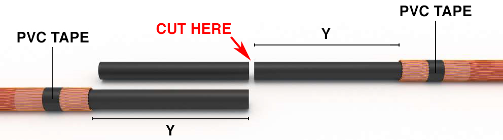 |
STEP 3:
Fold back the screen wires and bind temporarily with PVC tape. DO NOT CUT THE SCREEN WIRES! Cut the cable with the 250 mm overlap to the correct distance “Y” as listed in the table. |
|
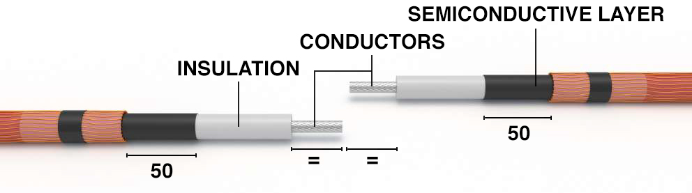 |
STEP 4:
Remove the semiconductive layer to a distance of 50 mm from the sheath cut. Take care not to damage the insulation. Bare the conductor for a length of inside depth of the connector for mechanical types or, in case of compression connectors, for a length of inside depth of the connector + 5 mm. Clean and degrease the conductor. |
|
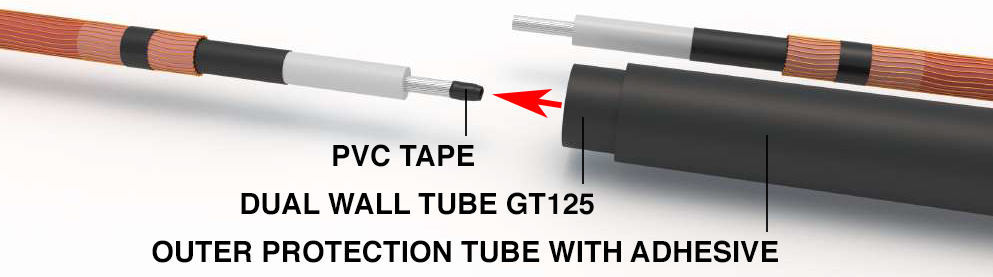 |
STEP 5:
As a protection, wrap few turns of adhesive tape around the conductor end. The cable preparation is finished. Now, slide all the heat shrinkable tubes onto the cable on one side of the joint. |
Cable Jointing Instructions
 |
STEP 1:
Ensure you followed all 5 steps of cable preparation above and both cables are ready for jointing. Important Note: All the heat shrinkable tubes must be on one side of the joint before moving to the next step of the jointing instructions. |
 |
STEP 2: Install the GPH Mechanical Cable Connectors (M95-300) onto the cable cores as per the manufacturer’s instructions. If using hexagonal compression links ensure that any sharp edges and flashing are removed from the connector with a file or abrasive cloth. |
 |
STEP 3:
Tighten and shear off the hexagonal bolts with the appropriate tool. In this example, for the outer and inner bolts, we used a SW13 battery-operated tool. You can also use a wrench or spanner. |
 |
STEP 4:
If using mechanical connectors make sure you fill up any indents left after shearing the bolts with void-filling mastic clay. |
 |
STEP 5:
Wrap the Dual Layer OM Stress Control Mastic Plate / Patch around the connector area. Centre the patch over the connector with equal distance at both sides. Do not squeeze the extremities. Ensure the mastic plate has bonded to itself by using the paper backing to apply mild pressure. |
 |
STEP 6:
Apply a layer of stress-relief OM Mastic Short Strip overlapping the semiconductive layer and the insulation of the cable. Approximately 10mm onto semiconductive layer and 10mm onto core insulation. Ensure the mastic has bonded to itself by using the paper backing to apply mild pressure. |
 |
STEP 7:
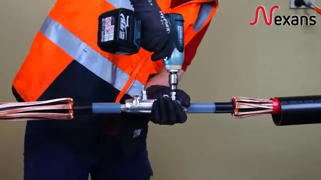
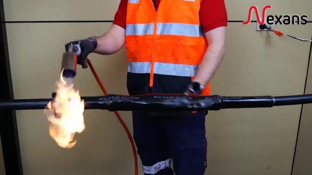
Position the GT125 Triple Layer Wall Tube in the centre of the joint, pre-heat the tube for a minute and start shrinking from the centre towards to the edges. Adjust torch to give a soft blue flame with yellow tip. To avoid over-heating of the heatshrinkable tube, keep the flame moving continuously and maintain an adequate distance from the tube (15-20 cm) with the angle of 45°. |
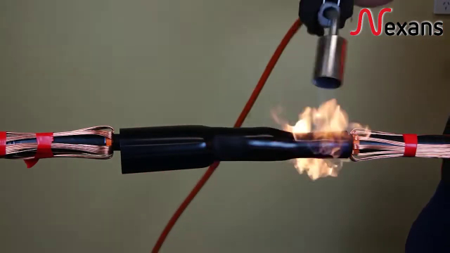 |
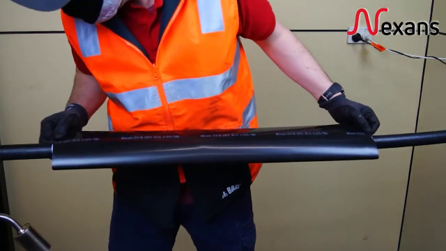
STEP 8:
Make circular moves around the tube to ensure a smooth and even final result, avoiding wrinkles along the surface. Continue the heatshrinking in circular sectors, while alternating on both sides. At the end of the work, the surface of the heatshrinkable tube must be smoothly wrapped around the joint. |
 |
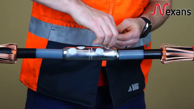
STEP 9:
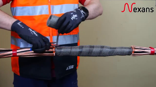
Wrap the whole joint with a metallic tape (Copper Screen Mess), using a 30% overlap, start and end on the edge of the triple wall tube. Make a knot to lock the metallic tape. |
 |
STEP 10:
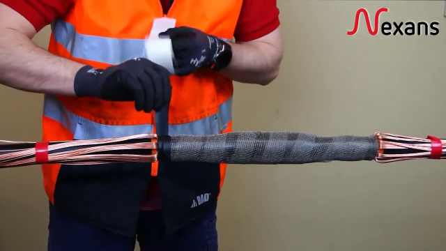
Apply a layer of NGAF Sealing Mastic at both ends of the copper screen mesh. |
 |
STEP 11:
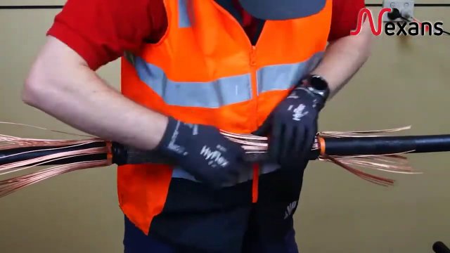
Remove the PVC tape previously applied to fix the screen wires (Step 3 of Cable Preparation). Fold back the screen wires towards the centre of the junction distributing them along the joint. |
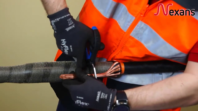 |
STEP 12:
Cut the screen wires at the desirable length, in order to be able to fit the screen connector in between and connect them. |
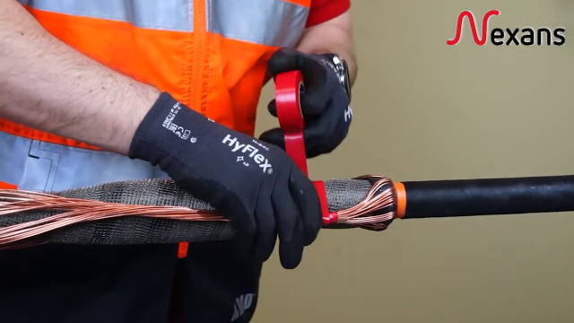
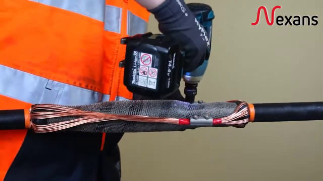 |
STEP 13:
Insert the Screen Connector and fix the screws, ensuring the correct torque is applied to shear off the connector bolts without damaging the screen wire. In this example we used an SW8 battery operated tool. |
 |
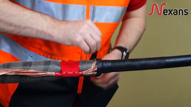
STEP 14:
Apply a layer of NAE Protective PVC Tape over the screen wire connector. |
 |
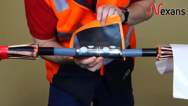
STEP 15:
Clean the abraded area of the outer sheath on both cables. Apply a layer of NGAF Water Sealing Mastic, starting 30mm from the edges of the outer sheaths and finishing at the screen wires, covering them for 50mm. |
 |
STEP 16:
Position the GT3 Outer Protection Tube over the centre of the joint and start shrinking from the centre towards the ends. |
 |
STEP 17:
When the joint is complete, allow it to cool before moving. |
Resin and Hardener Safety: First aid, spillage and storage guidance
When working with resin and hardener during the jointing process, it’s essential to be aware of the correct safety procedures in case of accidental exposure or spillage. Below is a practical guide to first aid, plus handling measures to protect you and those around you on-site.
Eye Contact
In the event of eye exposure, flush the eyes gently but thoroughly with clean water or an eye-wash solution for several minutes. Continue rinsing while keeping the eyelids open. If discomfort continues, seek prompt medical advice.
Fire Safety
Suitable extinguishing media include dry powder, foam, carbon dioxide (CO₂), sand, or earth. While water can be used in large quantities, it may not be the most effective for smaller fires involving these materials.
Ingestion
If swallowed, do not induce vomiting. Rinse the mouth thoroughly and encourage the person to drink plenty of water. Contact a medical professional straight away.
Inhalation
If vapours from the resin or hardener are inhaled and cause symptoms such as dizziness, coughing or shortness of breath, move the affected individual to fresh air immediately. If breathing difficulties occur or persist, seek medical attention.
Safe Disposal
– Mixed products: Once fully cured and hardened, the material may typically be disposed of with general waste, in accordance with local regulations.
– Unmixed products: Any unused or uncured product should be disposed of responsibly via a licensed waste disposal company or as advised by your local authority.
Skin Contact
If resin or hardener makes contact with the skin, rinse the affected area immediately using warm water and soap. Avoid using solvents to remove the material. Should redness, itching or irritation persist, consult a medical professional.
Spill Response
In case of a spill, absorb the material using sand, earth or a similar inert medium before cleaning the area with a solution of water and mild detergent. Always wear protective gloves when handling the spilled product, and ventilate the area if indoors.
Storage Guidelines
To maintain product integrity, store resin and hardener kits in a cool, dry environment at temperatures between 10°C and 35°C. Keep the product sealed, away from moisture and well separated from food, drink and animal feed. When stored correctly, the shelf life is approximately 24 months from the date of manufacture.
Nexans Solutions & Training Centre
Nexans JTS Heatshrinkable MV Cable Joints provide a cutting-edge solution for efficient and reliable cable installations. The above step-by-step cable preparation and jointing instructions constitute an installation guide for JTS cable joints. However, it is crucial to emphasise again that the installation process should be undertaken by competent individuals well-versed in electrical equipment and safety practices. Always adhere to the manufacturer’s instructions, visually inspect components, and dispose of waste responsibly.
Nexans have several comprehensive training centres all over the world, providing competency certified training for cable joints, separable connectors, terminations and other power accessories. They also offer installers the possibility to be trained at their premises or directly at construction sites. Contact us for additional information.
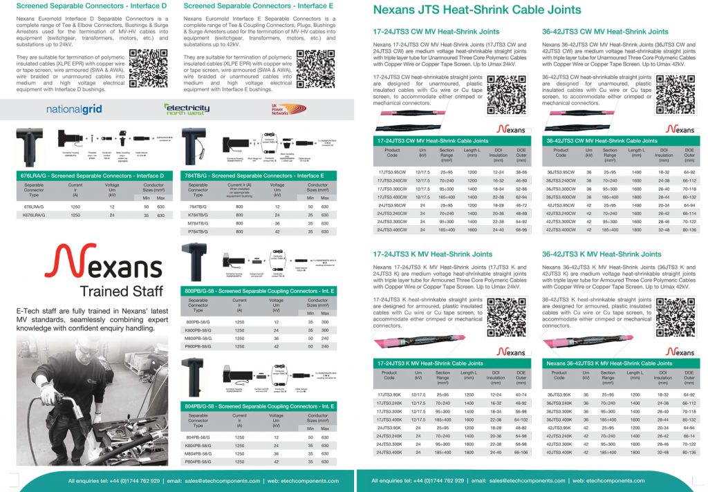
Check the full range here View Catalogue here
Our Technical Advisory Centre can answer any questions you may have regarding this range or any other power accessories needed for your project:
sales@etechcomponents.com | +44 (0)1744 762 929
E-Tech Components Medium Voltage Catalogue
From Heatshrink & Coldshrink Joints & Terminations to Custom Jointer Kits & Accessories, this NEW E-Tech MV Catalogue has it all! It’s comprehensive, easy to use and packed with reliable, innovative and high-performance MV solutions.
 |
 |
 |
 |
Additional Resources for Further Reading
- Nexans Expert Tool Kit – All the tools you need in one place!
- PFISTERER MV-CONNEX: Top-class technology from the inventor of the inner cone system
- Heat Shrink vs Cold Shrink: A Comparative Guide
Please note, we also supply KrimpTerm Jumbo Reels as part of our range of heat shrink consumables for cable jointing and termination.
| Datasheet: KrimpTerm Jumbo Reels |